


")


")


 kit Stainless")

")


 Long")
Engine management - The different parts
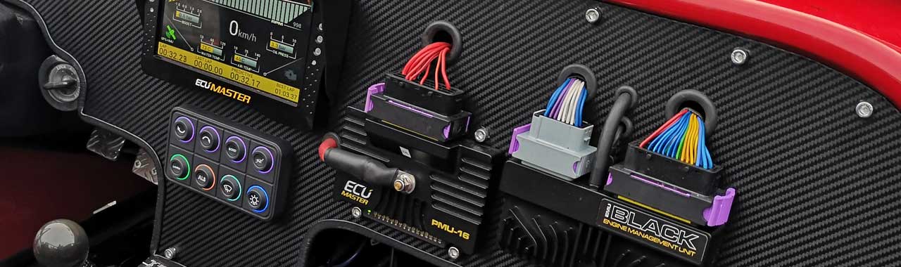
Here you get an overview of how an engine management system works and which parts are connected to the ECU.
The different parts are divided into headings as shown below. These headings together give a picture of which sensors, coils and ignition parts etc. can be used.
The various parts of the engine control system:
- Throttle Position Sensor (TPS)
- Electronic throttle housing / throttle
- Idle air control solenoid (IAC)
- Intake temperature sensor (IAT)
- Water coolant sensor (CLT)
- Exhaust Gas Temperature sensor (EGT)
- Ethanol sensor
- Pressure sensor
- Knock sensor
- Lambda sensor / Wide Band Lambda (WBL)
- Trigger sensor
- Ignition (Coil / spark plug)
- Fuel injector
- Fuel pump
- Cooling fan
- Speedometer
- Fuel level sensor
- Relay
- Other electrical system (PDM)
1 ▼
Throttle Position Sensor (TPS)
TPS sensors are mounted on cable controlled throttle bodies.
A throttle sensor is mounted on one side of the throttle housing shaft and tells the control system throttle position calculated in % from 0-100.
The part connecting the TPS against the throttle shaft is D-shaped and is called a pivot. The D design allow the throttle body axle to turn the TPS. Most throttle housings have this type of attachment. Sometimes a custom fitment of the sensor housing itself need to be made as the hole pattern can vary.
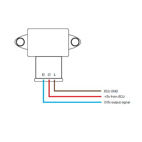
A TPS sensor usally connect with 3 pins:
- ECU ground
- +5volt sensor supply from ECU
- Signal to ECU (0-5V)
2 ▼
Electronic throttle housing / throttle
When an electronic throttle body housing is used, no external position sensor is needed. This is built into the E-throttle housing. Many E-trottle bodies also have two tps sensors and E-throttle pedals have two potentiometers. One main sensor and one for backup. Keep that in mind when setting up the system.
Electronic throttle bodies do not work without an electronic accelerator pedal connected
E-throttle bodies mainly have 6 pin connectors
- Motor +
- Motor -
- TPS 1 (0-5V signal to ECU)
- TPS2 (0-5V signal to ECU
- +5V from ECU
- ECU ground
E-throttle accellerators often have 6 pins, check how each pin should be connected for your particular pedal. The throttle pedal has two potentiometers for TPS which are connected to analog inputs on the ECU. If, however, one of these is PWM control, this is connected to a digital input to the ECU.
3 ▼
Idle air control solenoid (IAC)
An idle motor has oine air input and one air output which are connected to each side of the throttle body. In this way, it can control the engine idle speed by allowing air to pass into the engine even though the trottle body is closed. The alternative is to have a set screw which means that the throttle body cannot close completely. This is controlledby the ECU when using an E-trottle
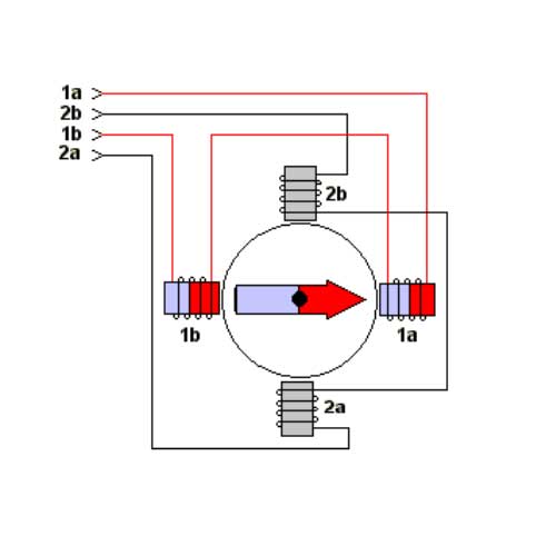
There are idle motors with 2,3,4,5 and 6 pins.
- 2 pin is connected with one pin to +12V ignition voltage and the other to ECU Analog. The polarity can be changed on the pins or through the software.
- 3 pin is connected with one pin to ground. The other two pins are connected to +12V ignition voltage and the other to ECU Analog. The polarity can be changed by swapping the +12V and ECU pins or through the software.
- Other idle air solenoids are called "stepper" motors. One connection example can be seen in the picture.
4 ▼
Intake temperature sensor (IAT)
Intake air temperature is measured in the intake pipe or plenum chamber by fitting a sensor to read the intake air temperature. Intake temperature is an important parameter to take into account for the engine control system to be able to adapt to the current environment. The IAT sensor is not a must to make the system work but it is something that is recommended to get the most out of the engine efficiency.
Intake temperature sensors have two pins and are not polarity sensitive.
The IAT is connected as follows:
- ECU ground (Sensor ground)
- Signal to ECU (Specific temperature)
Sometimes the values from temp and pressure sensors can "flutter". Then try to activate any built-in filters in the software and increase the value slowly until it stabilizes. If you have to increase a lot, the sensor may be mounted in a bad position.
5 ▼
Water coolant sensor (CLT)
Except of showing the water temperature, a water temperature sensor is used to electronically activate a cooling fan or trigger a safety function. The water temp sensor is mounted on the engine before the thermostat, but if there are two temp sensors, the second one is mounted after the thermostat on the "cold side"
Water temp sensors have only two pins as the intake temp sensor and are not polarity sensitive.
CLT are connected as follows:
- ECU ground (Sensor ground)
- Signal to ECU (Specific temperature)
Note that sensors are not torqued too hard as they are sensitive. The sensor body can negatively affect values or completely break.
6 ▼
Exhaust Gas Temperature sensor (EGT)
Exhaust gas temperature is measured in the exhaust manifold and exhaust system. Several EGTs can be used to, for example, log temp on separate cylinders. This type of sensor measures up to approximately 1300 degrees celcius and is called type K in the aftermarket as this is by far the most common, although there are variants.
An EGT amplifier must be used to connect this type of sensor to an engine management system. Some ECUs have this built in and then no amplifier is needed..
Connection of EGT amplifier:
- ECU ground
- Signal to ECU (0-5V)
- Chassis ground
- +12V ignition
Connection of EGT:
- ECU ground
- Signal to ECU (0-5V)
7 ▼
Ethanol sensor
Ethanol sensor is used to measure the ethanol content in the fuel so that the engine management system can compensate for more or less ethanol. Fuel temperature can usually also be measured through these sensors.
The sensor is mounted on the return line as these usually have a small internal diameter and can be a restriction if it is mounted on the pressure side (the engine fuel supply line)
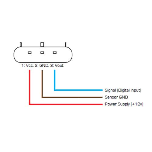
The sensor uses a digital signal with varying pulse/work ratio and is connected to a digital input to the ECU
- Signal to ECU (Digital)
- ECU ground
- +12V ignition
8 ▼
Pressure sensor
Pressure sensors are used in various wys and measure the pressure of air, oil, water, fuel and other liquid media.
A pressure sensor for air is called MAP sensor (Manifold Air Pressure). These are most often used for engine management systems instead of air flow meters where pressure is measured instead of air flow and gives a more accurate result.
- ECU ground
- +5V from ECU
- Signal to ECU (0-5V)
A pressure sensor should not be mounted directly on the engine block as they cannot handle certain frequencies / vibrations that some engines produce. Instead, use a remote installation on the side of the engine.
9 ▼
Knock sensor
A knock sensor detects "knock" / "spiking", or as it actually is - a early detonation of the air / fuel mixture ignited by heat and not by spark plugs.
The sensor is mounted directly to the engine block to be able to recognize these early detonations. Most often two sensors are used to be able to cover a larger area and recognize misfire better.
The knock sensor has two pins. Is not polarity sensitive, and is connected to dedicated inputs to the ECU. In other words, the ECU must support knock regulation / sensors for it to work.
10 ▼
Lambda sensor / Wide Band Lambda (WBL)
A lambda probe measures the lambda value in the exhaust gases, how efficient the combustion of the air / fuel mixture is. Stoichiometric mixture is Lambda 1. One can also measure this in AFR readings. Narrow-band lambda is used on OEM vehicles and this only senses when the value passes above or below lambda 1. A wide-band lambda, on the other hand, can read a value in a large area around lambda 1. Eg Lambda 0.6-1.4.
Wide band lambda sensors is the ones used in aftermarket installations as lambda values must be read accurately when tuning the engine control unit software. This lays the foundation for how well an ecu can be programmed.
Two common types of wide band lambda sensors are LSU 4.2 and LSU 4.9.

LSU 4.2
This sensor measure rich fuel mixtures better (below Lambda 1). Often used in conjunction with aftermarket control systems (ECU)
Bosch part: 0258007057
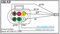
LSU 4.9
This sensor measure lean fuel mixtures better (above lambda 1). Often used together with separate lambda meters.
Bosch part: 0258017025
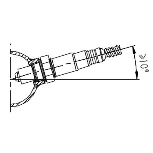
Installation of the lambda sensor should ensure that the measuring probe itself points slightly downwards. This is to prevent moisture damaging the lambda sensor.
Installation preferably takes place 30+cm from the turbo / engine, away from the most intense heat.
11 ▼
Trigger sensor
Trigger sensors are used on the crankshaft and camshaft to know where the engine position is for the ignition and fuel to be set optimally. These sensors measure on some kind of trigger wheel that has one or more "tooth" missing. In this way, the ECU knows when one revolution has been completed. When this trigger is used on both crankshaft and camshaft, the ECU knows exactly where the camshaft is in relation to the crankshaft and can then control ignition / fuel injection "sequentially", which is more efficient. There is a lot of information about the subject. Trigger signals in particular.
Trigger wheels that are mounted on the crankshaft usually have a 60-2 or 36-1 pattern. Camshaft (Home signal) only needs 1 signal per revolution to work.
Hall sensor / Opto sensor (Digital 3 pin)
- +5V/+12V (depending on sensor)
- ECU ground
- Trigger signal to ECU
VR-sensor (Analog 2 pin)
- ECU ground
- Triggersignal to ECU
12 ▼
Ignition (Coil / spark plug)
The ignition system provides power to the spark plugs that ignite the air / fuel mixture in the combustion chamber. Better ignition systems provide better conditions for igniting a rich (much fuel) air / fuel mixture.
Ignition coils need the energy source directly from the battery. The control system cannot "drive" these. That is why it is said that an ignition module is needed. This unit can be separate (stand alone) or built into the ignition coil. In short, it is a device that allows separate power supply as the ECU cannot handle this.
The coil circuit are usually fused with 15Amps and are connected on the same power supply as the ECU itself.
Waste spark
The engine only have one crankshaft trigger and does not know where on the 360 degrees the engine is located. The spark plugs then ignite 2 times per revolution (360 degrees). The ignition coil also needs to discharge/upload twice per revolution.
Sequential ignition
If a trigger on the camshaft (Home signal) is used in conjunction with the crank trigger, the engine know the exact position. The spark plugs then ignite only 1 time per revolution (360 degrees). The ignition coil therefore only needs to be discharge / load 50% of the time compared to waste spark. This system does not stress the coils as nmuch, plus separate ignition coils can be used and the system becomes more efficient.
Rich fuel mixture / lower lambda is harder to ignite. Therefore, greater demands are placed on the ignition system with a tuned engine.
13 ▼
Fuel injector
Injectors inject fuel into the engine. The fuel pump feeds the injectors with fuel which open and close using a signal from the engine management. The top of the injectors are mounted in a fuel rail. Then the bottom of the injector are mounted to the intake manifold. The electrical connector is a two-pin version and the injector itself is not polarity sensitive. These are linked to the engine management system (ECU) which opens and closes the fuel injectors more or less / faster or slower depending on engine load and rpm.
Injectors are connected to +12v ignition and the circuit is usually fused with around 15 Amp.
There are different types of injectors such as top-fed, side-fed, high-impedance, low-impedance, etc. More information about this is available separately.
The two pins are connected as follow:
- +12V ignition
- ECU injector outlet (signal)
14 ▼
Fuel pump
A fuel pump feed the injectors with fuel through fuel lines up to the fuel rail, where the injectors are mounted. A fuel pressure regulator maintain a given pressure to the injectors.
There are in-tank fuel pumps for installation inside the fuel tank (internal fuel pump) and there are pumps for external installation -mounting outside the fuel tank (external fuel pump). Regardless of the model, these are installed with suitable brackets for proper operation. The inlet is connected to a pre-filter or directly to the fuel tank. The outlet is connected to a fuel filter which is then led on to the fuel rail and fuel pressure regulator.
The fuel pump is controlled by the ECU through a relay (so-called fuel pump relay). Note. Cable dimensioning to the fuel pump need proper sized cables. The electrical connector has two pins. One is connected to +12V and the other to chassis ground.
15 ▼
Cooling fan
The engine management system can also control the radiator fan so that it turns on and off depending on other triggers. In the same way that a fuel pump is connected with a relay to the ECU, a cooling fan is also connected.
The cooling fan is most commonly mounted on the water cooler (radiator) and connected through a relay to the ECU.
There is also another variant of the fan that is connected to the engine with a so-called visco-connection. This is not usually used in performance cars.
16 ▼
Speedometer
The original speedometer can be connected to an aftermarket control system if the OEM gauge is pulse-controlled. Meaning that a pulse is sent out from the ECU to the gauge and the pace increase along with the speed. If original instruments need this type of signal to work, it is possible to connect it to the aftermarket ECU.
This is checked by measuring whether a pulse from the OEM control unit reaches the speedometer / instrument.
This is then adjusted in the software by increasing or decreasing the frequency of the pulse with a GPS or other speed signal as reference.
This is then connected to a digital input on the aftermarket control system.
17 ▼
Fuel level sensor
This part measures the fuel level.
There are many variants from OEM that can be used. But the easiest and most common sensor type in the aftermarket is a 0-90 Ohm sensor that has bolt pattern with 5 holes and CC measurement of 53mm (most common bolt pattern)
The level sensor has two pins NOTE These are polarity sensitive!
- ECU ground
- Signal to ECU (Analog)
18 ▼
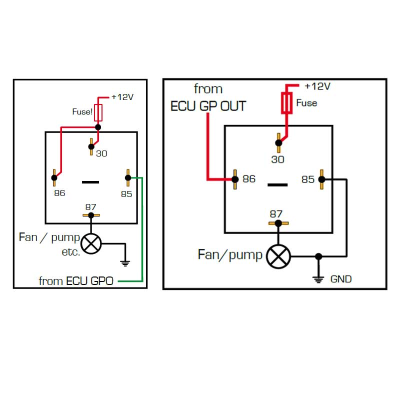
Relay
A relay is used when you have a part that requires a bigger current, while in e.g. a car you want to control this with a small current (ECU signal).
You can think of it as a switch. When the control system wants to activate a fan or fuel pump, a signal (small current) is sent to a relay which is activated like a switch and then supplies the part with power (big current)
There are also solid state relays. The function is the same but with no internal moving parts.
It is possible to send both a +12v (plus-controlled) and an ground (Ground-controlled) to a relay denpending on the installation.
Two different connections is shown in the pictures.
19 ▼
Other electrical system (PDM)
There are additional parts that are connected to an engine management system such as a power distribution module (PDM), PWM boxes, keypads, CAN control, EGT sensors, G-sensor, etc., etc. but the basis is the same. They are connected to a digital or analog input. The specific function for each in/output can then be ste individually in the control system software. Thereby one can also use the signal sent in to send it out or manipulate another signal.
▼
▼
-
Engine management / Electric
- Engine control system: The various parts available
- Ignition System Information
- Install motor control
- Pressure sensor - Information
- Temperature sensor - Information
- Buttons - Switches - Information
- Connectors - Information
- Cooling fan car - Information
- Exhaust gas temperature sensor - EGT Sensor
- Lambda sensor - Wide band lambda
- Relay - Information
- Relay box - Fuse central
- CAN protocol - Canbus
- Ethanol sensor - Information
- Gauges and Dash
- Trigger sensor information
- Dimensioning of cable [and fuse size]
- Distributor Problems (And Solution)
- How does an Ignition Coil work?