


")


")


 kit Stainless")

")


 Long")
Trigger sensor information
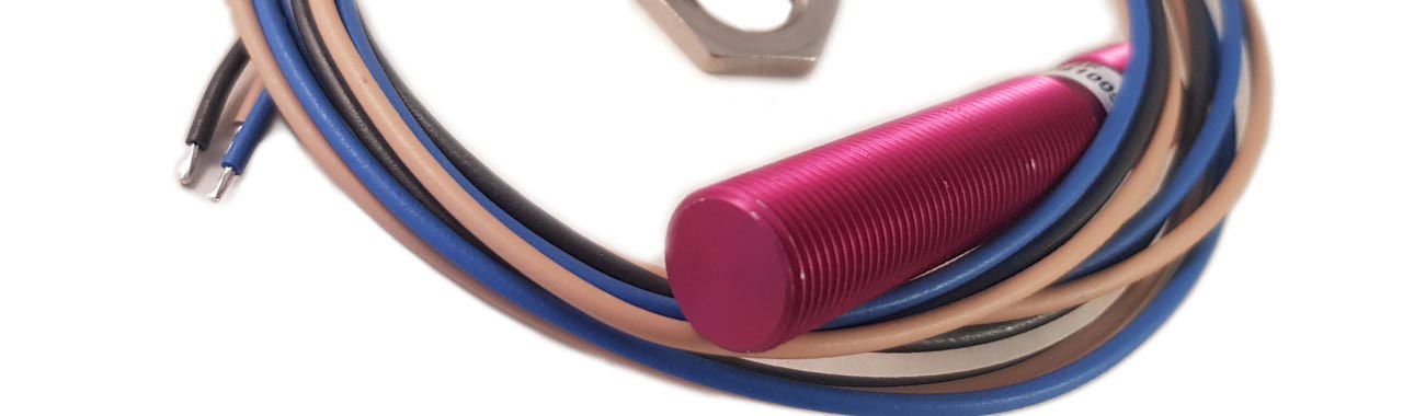
Here you get an overview of how a trigger sensor works.
- What is a trigger sensor?
- Different types of trigger sensors
- Sensor wiring
- Trigger sensor installation
- Problems
1 ▼
What is a trigger sensor?
A trigger sensor / tachometer reads as the name suggests trigger points. These trigger points can be found on a camshaft, crankshaft, drive shaft, prop shaft or on anything else that needs to be read. This signal is then sent to a control box (ECU).
2 ▼
Different types of trigger sensors
There are different names for these sensors such as trigger sensor, rpm sensor, camshaft sensor, crankshaft sensor optosensor, cam sensor, home sensor, flywheel sensor and so on.
Two types are used:
- Digital sensor (Hall sensor / opto sensor)
This sensor has three cables, one "plus", one "minus" and one "signal" - Analog sensor (VR-sensor)
This sensor has two cables, one "plus" and one "minus"
3 ▼
Sensor wiring
The sensor wiring is general to most control systems but may differ slightly depending on the manufacturer.
- Digital sensors (Hall sensor / opto sensor) - three cables
- Plus (+) - 5 or 12 volts depending on the type of sensor
- Ground (-) - sensor specific ground point towards the ecu intended for trigger sensors only
- Signal - sensor specific input to ECU e.g. trigger / home / digital in
- Analog sensor (VR-sensor) - two cables
- Signal - Sensor specific input to ecu e.g. trigger / home / VR in
- Ground (-) - Sensor specific ground point towards the ECU intended for trigger sensors only
Trigger sensors are sensitive to interference and must not be connected to the chassis - Always connect trigger sensors directly to the control box (ECU)
4 ▼
Trigger sensor installation
As previously mentioned, a trigger sensor is sensitive to interference. Therefore, installation is extra important to avoid problems. The bullet points that are important during assembly are:
- Mount the sensor to a rigid bracket that cannot move or flex
- The trigger wheel / reading points must not move or flex
- About 1mm between sensor and reading points
- Mount the sensor centered against the reading points - no offset mounting
- Run the wiring separately from other power supply / ignition system to avoid interference
5 ▼
Problems
Trigger problems are very common and are usually due to one of the points below. Troubleshooting is done most easily in a data logger (preferably built into the ECU)
- The sensor bracket moves or flex
- The trigger points moves or flex
- The trigger points are not clear enough because debris, rust, diameter, rpm, unbalance/self-oscillation occur
- Distance between sensor / trigger point too long
- Sensor is not centered to reading points
- The wiring is disturbed by power cables / power supply or ignition system
A bad trigger setup can maintain a strong enough signal at low rpm. But when the rpm increase, the problems occur. These can be a combination of the above points. So it doesn't have to be the only reason for a bad signal / problem.
Small diameter of trigger disc, more teeth, longer distance to sensor easily causes interference.
▼
▼
-
Engine management / Electric
- Engine control system: The various parts available
- Ignition System Information
- Install motor control
- Pressure sensor - Information
- Temperature sensor - Information
- Buttons - Switches - Information
- Connectors - Information
- Cooling fan car - Information
- Exhaust gas temperature sensor - EGT Sensor
- Lambda sensor - Wide band lambda
- Relay - Information
- Relay box - Fuse central
- CAN protocol - Canbus
- Ethanol sensor - Information
- Gauges and Dash
- Trigger sensor information
- Dimensioning of cable [and fuse size]
- Distributor Problems (And Solution)
- How does an Ignition Coil work?