


")


")


 kit Stainless")

")


 Long")
Turbo - Connections
Here we walk you through the connections that are suitable for your turbo. Exhaust outlet, oil supply, water connections and so on
Introduction
A guide to the various connections available on a turbo. Below we will take a closer look how the different connections look like.
A turbo has the following connections and the only difference is if the turbo is not water cooled, then there are no water connections.
- Compressor inlet
- Compressor outlet
- Vacuum connection
- Oil inlet
- Oil outlet
- Water inlet
- Water outlet
- Exhaust inlet
- Exhaust outlet
Compressor inlet
An air filter or a hose led from an air filter / air filter box is mounted on the compressor inlet
Air filter
The air filter is mounted directly to the turbocharger inlet or to a hose that connect an air filter or an air filter box.
Installation of air filter / hose
Installation of air filter or hose is done with hose clamps as almost exclusively all compressor inlets on turbochargers are made for hose connection. You can also remove the compressor cover from the center part and weld on a pipe on which the air filter is then mounted.Different air filters
Different types of air filters are available to suit different applications or turbochargers. You can categorize them as Motorsport, Dry-flow and turbo guard.
- Motorsport
A so-called motorsport filter flow best as it simply only has ~2-5 layers of filter surface. Fewer layers also provide better flow per cm2. and is better suited for motorsport and where you have more engine power or a large engine volume. Therefore, it is said that these should be oiled so that dirt gets stuck / filtered more easily. - Dry Flow
These filters filter best as they have more than ~5 layers of filter surface. A dyflow filter is often used as an "off-road" filter where high demands are placed on filtration. No oil needs to be used either, so the filtration is still good due to more layers of filter surface. - Turbo guard
A turboguard filter only has a coarse-mesh as protection so that larger objects such as grave do not accidentally enter and damage the turbo. Turbo guard filters are most often used in drag racing where the requirements for filtration are less due to a cleaner environment and less running hours.
Air filter size
The size of the air filter is usually determined by the space available. First you choose the type of air filter and then you choose such a large air filter that fits. Then there is never the risk that the air filter restrict the flow. The flow in is very important and restricted flow can be a reason for lack of power.
Compressor outlet
The compressor outlet is mounted together with the engine intake
Pressure pipes
The turbocharger outlet is mounted against the pressure pipes that are led into the engine.
Pressure pipe installation
From the turbo to the engine, the air is led by pipes. These are called pressure pipes as the turbo builds up a pressure that overcharges the engine. The pressure pipes are first led through an intercooler that cools the pressurized air and then further through the throttle body / intake that is located on the engine.These pressure pipes are connected with silicone hose and hose clamps or hurricane clamps that provide a secure connection that does not jump apart in the event of jerks and vibrations.
Different pressure pipes
Pressure pipes can be built with different types of pipes. Aluminum is most common due to its weight, but there are also examples where steel and stainless steel are used. The pressure pipes in aluminum can be divided into three categories to choose from. Polished pressure pipes, untreated pressure pipes 3mm and untreated pressure pipes 2mm
- Polished pressure pipes
These pipes are 2mm thick and have a treated / polished surface that gives a good look. The surface can be sanded / scraped off if you want a raw surface. The different pipes are available in straight pipes, 30 degrees, 45 degrees, 90 degrees, 135 degrees and 180 degrees. This makes these pipes very suitable for the construction of pressure pipes. The bends are manufactured with a long radius. - Untreated pressure pipes 3mm
These pressure pipes are strong and are available in straight pipes and 90 degree bend short radius (1.5xD). - Untreated pressure pipes 2mm
These pressure pipes are light as the polished ones but offer in addition to the straight pipes above 90 degrees bend in a short radius (1.5xD). These can be cut to get 45 degrees or another angle
Pressure pipe size
The size of pressure pipes is usually determined by the turbo's compressor outlet and the throttle body. If the turbo compressor outlet is 2" and the throttle body 3", a pressure pipe is used in between. 2", 2.5" or 3". Cone the pipes up or down with the help of aluminum cones.
Vacuum connection
The vacuum connection is mounted together with the engine intake / pressure system
Vacuum connection
The vacuum connection is connected to the intake / pressure pipe with a vacuum hose made of silicone or pneumatic hose.
Installation of vacuum connection
The turbo vacuum connection is connected to the wastegate. This can be connected directly to the turbines wastegate but will then only provide basic charge pressure / the pressure that the wastegate spring can maintain. If you connect a boost pressure control on the hose between the turbos vacuum connection and the wastegate, you can control the turbo boost pressure with the help of this control. It is available as an analogue manual / fixed valve or electric which is controlled by the engine control system (ECU).
The vacuum connection is not ready on all turbochargers because some want to mount the control on the pressure pipes instead. But if the connection is not ready, the compressor cover always has certain places that are intended for drilling and threading in where there is more goods. Then the compressor cover is removed before modification is made.
Various vacuum connections
There are two types of vacuum connections that are commonly used. Silicone hose and pneumatic hose.
Silicone hose is soft, flexible and can withstand high temperatures due to. that it is made of silicone material. Mounting is done on classic barb fittings as the hose is flexible and seals well over a barb fitting. This type of hose is usually original mounted on cars.
Pneumatic hose is rigid, not so flexible and does not withstand high temperatures because it is made of plastic. The assembly is done with a so-called push-lock fitting. Assembly is made easy by pushing the hose into the fitting and then it is locked. When disassembling, a collar must be held down to allow the hose to come loose. This hose is usually mounted in industries.
Vacuum connection size
Hose
The most common size of hose used for vacuum control is 4, 5 and 6mm silicone hose and 1/4" and 6mm pneumatic hose.
Fittings
The most common thread that vacuum fittings use is 1/8" NPT but some turbochargers have M8x1 or M10x1. There are also products with 1/16" NPT thread but is then recommended to be threaded up to 1/8" NPT so it does not become a restrictor .
Oil inlet
Oil in is mounted together with the engine oil system (pressure duct)
Oil feed
The turbo oil supply is led from where the engine original turbo is fed with oil, or alternatively the engine main line with oil pressure.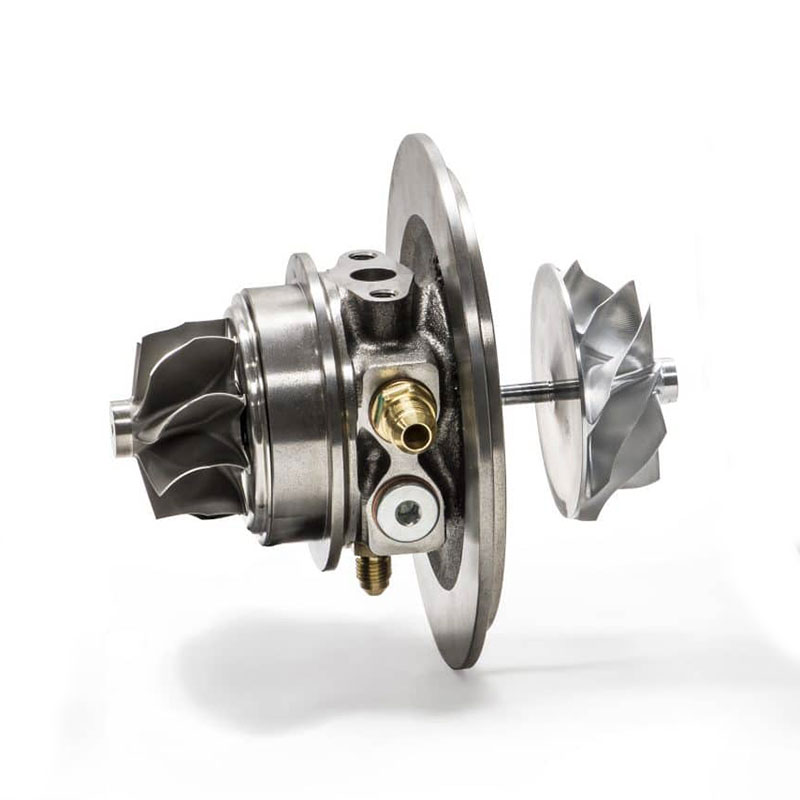
Turbo oil feed installation
Turbo oil inlet can be mounted in many different ways where the fittings vary greatly depending on the engine. But a rule of thumb here is to always take the oil supply from where it was originally fitted -if it is a turbo engine. If it is not a turbo engine from the beginning, an oil channel must be located directly from the oil pump (the main channel) so that no oil pressure drop occurs.
Then just connect the turbo and engine with a suitable pipe or hose. What you should bring in mind is that the turbo get very hot so a hose that can withstand higher temperatures should be used. A heat shield over a hose or pipe closest to the turbo can also be used to advantage to prevent heat radiation, especially from the turbo exhaust housing.
An extra oil filter can be used on the turbo oil supply as an extra protection against dirt entering the turbo. When an extra filter with fine filtration is mounted on a journal bearing turbo, it can restrict the flow depending on other parameters. Therefore, make sure that you do not use a filter that is too small in relation to the flow.
Different turbo oil feeds
The oil supply can be built in both pipe and hose, which is best for the application. Hose is usually the simplest as this can be shaped as you want and is not as difficult to fit as a pipe. a pipe, on the other hand, is durable and looks professional. OEM use almost only pipes for turbo oil supply.Oil feed size
The size of the oil supply for the turbo is almost exclusively AN4 (1/4"), this is because an AN3 (1/8") hose that gets a little longer can act as a restrictor. In addition to this, the most important factor to keep in mind when supplying turbocharger oil is the following:
Do you use a ball bearing turbo or a journal bearing turbo?
Ball bearing turbo
A ball bearing turbo needs a restrictor at the oil inlet as the turbos bearings should not have oil pressure but only a flow. This is not adjusted with the size of the hose. This is adjusted with the adapter between turbo and hose and is called oil inlet restrictor.
Journal bearing turbo
A journal bearing turbo need full oil pressure just like the engine bearings. Oil inlet restrictor should NOT be used here - then turbo bearings will fail.
Oil outlet
Oil drain is mounted together with the engine block or oil pan
Oil drain
The turbo oil drain is led by a hose or pipe back to the engine / oil pan.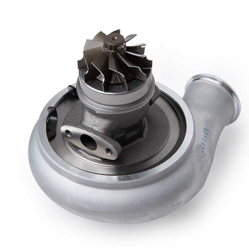
Oil drain installation
The oil that is led through the oil supply to the turbo to lubricate is then led back to the engine through the oil return. Turbo oil return is mounted where the original outlet for oil return is located. If the engine does not have a turbo original, oil return is mounted in a suitable place for service and inclination on the oil return. Note that the slope of the oil return should preferably be above 45 degrees to evacuate oil properly. This is not always possible but is a guideline.
On an engine that has not had a turbo originally, the oil return can be mounted both above and below the oil level. The most important thing here is that the turbo is mounted so high that the oil level can never be pushed up completely in the oil return at acceleration, brake or turn as the turbo directly would be filled with oil and pushed this into the exhaust system and pressure pipes.
Different oil return installations
An oil return can be built with both hose and pipe. OEM installations usually use pipes, but this can be more difficult to install, so hose is most often used in the aftermarket or for turbo conversion / new construction. If a hose is used, ordinary classic hose and hose clamp can be an alternative, but something that is very popular is to use ANfittings and AN-hose as an oil return.Oil drain size
The size of the oil return is controlled by how much oil is fed to the turbo. A ball-bearing turbo does not need as much oil as a plain-mounted turbo and can therefore also use a smaller dimension on the oil return.
Ball bearing turbo
Generally, an AN8 (1/2") hose is used for oil return to a ball bearing turbo.
Journal bearing turbo
AN10 (5/8") or preferably AN12 (3/4") hose is used here to be able to completely evacuate the large oil flow that comes with a journal bearing turbo. a rule of thumb here is to use a hose with an inner diameter as the turbo oil drain hole, preferably larger.
Water in / out
Water in / out is mounted together with the engine water system
Water feed
Turbo water cooling is connected to the engine water system.

Installation of water in and out
Turbochargers that have water cooling are cooler when the engine water line is used to cool the turbocharger bearings. The water connections between the turbo and the engine are connected by a hose or pipe, just like the turbo oil supply and oil return. These are connected where the original turbo took water from. If the engine did not have a turbo original, water must be taken after the water pump (on the pressure side) and led back before the water pump (on the suction side). In this way, a flow through the turbo is created. The water pipes can flow through the turbocharger in any direction, there is no inlet / outlet.Different water pipes
If a turbo is fitted original, the lines can be adapted to fit the OEM installation. If a hose clamp was used, you do it even now. or if a thread is used, you do it even now and then advantageously use A-fittings. Hoses are again a very flexible solution and provide a nice installation.Water pipe size
The size of water pipes is at least 3/8 "(AN6) but also 1/2" (AN8) can be used. For cooling the turbocharger, the size of the water pipes is not of the utmost importance, but you can use a smaller hose (AN6) to make the installation smooth. The cooling capacity is instead affected by the other components of the cooling system and not the size of the cooling hoses.
Exhaust inlet
Exhaust inlet is mounted against the exhaust manifold
Exhaust manifold
The turbo is mounted on the exhaust manifold flange / exhaust flange using a v-band clamp or bolted depending on the type.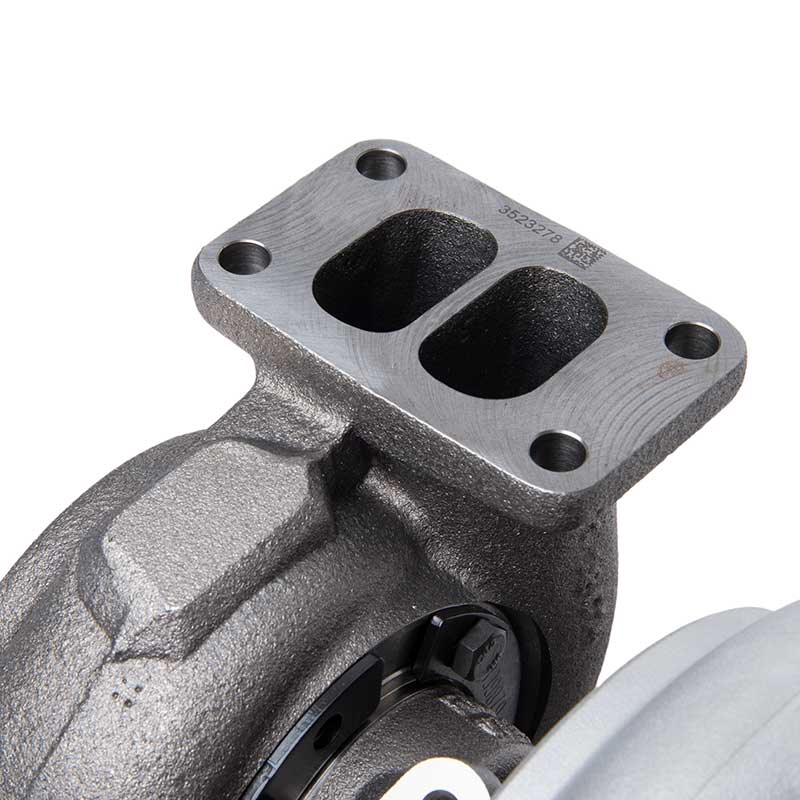
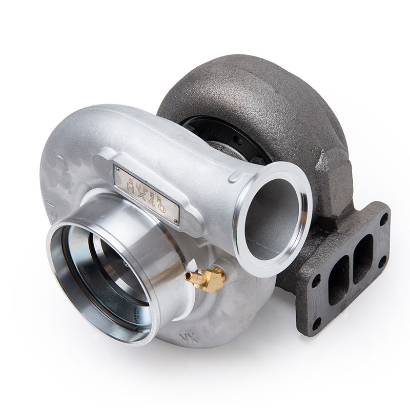
Turbine Installation
The turbine exhaust inlet is mounted on the manifold. This is where the engine exhaust gases supply the turbo with energy. Here it is important that the transition is smooth and fine so that turbulence is not created unnecessarily. A steady flow is important to maintain the efficiency of the turbo.Different turbine inlets
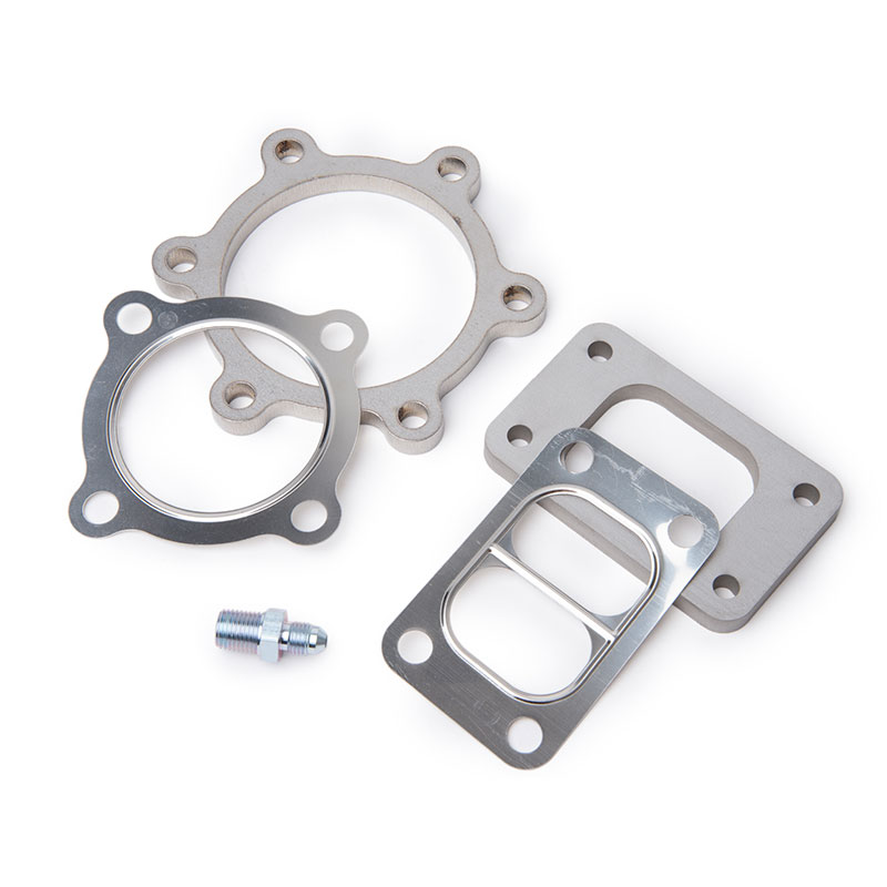
The exhaust inlet has a manifold flange that is available in various standard connections such as T25, T3, T4, T6 and V-band, among others. Here you have to adapt the manifold to the connection of the turbine if the manufacturer of the turbocharger does not have the option to configure the exhaust inlet on the turbine housing. The various connections are also available as single entry and twin entry.
Singel entry
This connection has a large hole where all exhaust gases pass down into the turbo exhaust inlet.
Twin entry
This type is used if you have an even number of cylinders (4, 6 or 8) and then you can with the help of the manifold design and the engine ignition sequence lead the exhaust gases together in a smoother flow that creates a more efficient turbo.
Turbine inlet size
The size of the exhaust inlet usually depends on how much power the turbo can produce. That is, how much flow is allowed. The different flanges T25, T3, T4 mentioned are also as the figures indicate in order of magnitude where T25 is smallest and T6 is largest. There is also a V-band connection but then this is called a 2" V-band or 3" V-band and the size is stated in clear text.
Exhaust outlet
The exhaust outlet is mounted against the downpipe / front exhaust pipe
Downpipe
The turbine exhaust outlet is mounted together with the exhaust system / downpipe using an exhaust flange.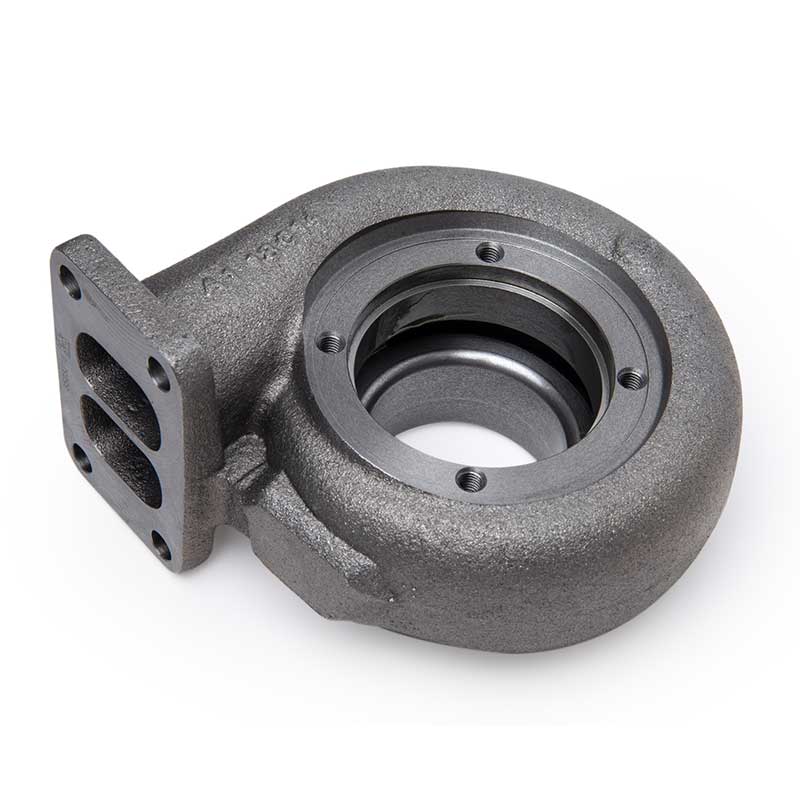
Installation of downpipe
The exhaust gases are led out through the exhaust outlet and into the exhaust system. The front part of the exhaust system that is mounted to the turbo is also called the downpipe. This can be made of the material used by the rest of the exhaust system. Materials in Steel or stainless steel are available.Different types of exhaust flanges
There are different exhaust flanges depending on the turbocharger and manufacturer. These are sorted on turbochargers and number of bolts or if it is a V-band, it is sorted by size. At least two to three parameters should be used to make sure you get the right connection. eg Garrett, 3" v-band and exhaust inlet.
Manufacturer
Some examples where you sort by manufacturer are Garrett 5 bolt, Holset 6 bolt or Mitsubishi 3 bolt. These in turn can have more options so it is important to measure the inner diameter of the holes / pipes and the cc dimensions of the bolt holes.
V-band
V-band connections usually only have one size that fits, for example, 3" V-bands. But even here, there can be several variants, such as the design of the flange.
Other
Other flanges that are available indicate the inner diameter of the center hole and the cc dimensions of the mounting bolts to determine what fits.